.svg)


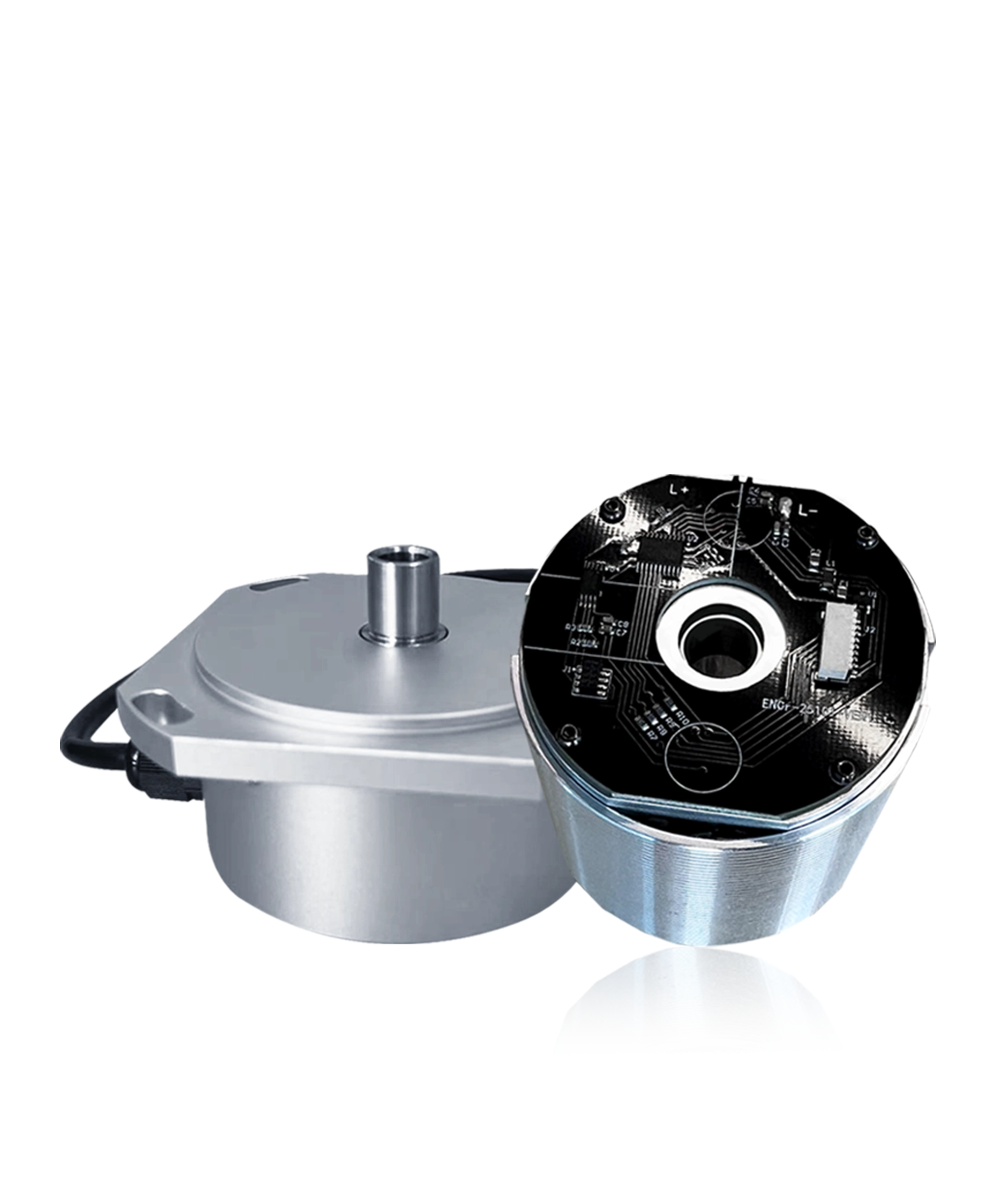
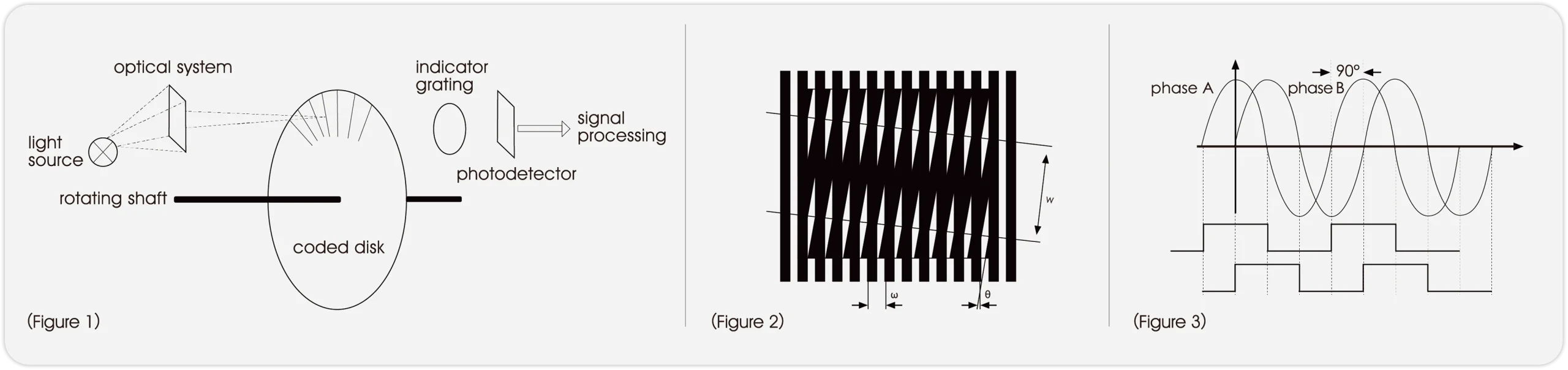
The encoder typically consists of a rotating shaft, coded disk, light source, indicator grating and photodetec tor in Figure 1. Generally speaking, the disc is mounted on the encoder shaft and rotate corresponding to the optical system. The disc uses opaque and transparent segments, so does indicator grating. When the paralleled LED light shines through the disc and the indicator grating and received by the photodetector, moiré fringes are formed in Figure 2. After processing the signal of the moiré fringes, the detector can obtain two sets of orthogonal signals ( A and B) in Figure 3. Consequently the processor gives rise to the angle of the rotating shaft in the counting operation.